//ATS = 14 75 A2 A8 03 80 69 AF 02 04 01 36 00 02 0A 0E 83 3E 9F 00 B0 BE
//--ATS length 0x16(22) bytes
//ATS structure includes length byte TL, format byte T0, interface byte
//--TA1, TB1, TC1, history byte and 2 bytes CRC. The ATS structure is as follows:
//----TL is the length byte of ATS(mandatory), its length includes itself but does not include the CRC
//----------The maximum size of the ATS shall not exceed the indicated FSD. Therefore the
//--------------maximum value of TL shall not exceed FSD-2.
//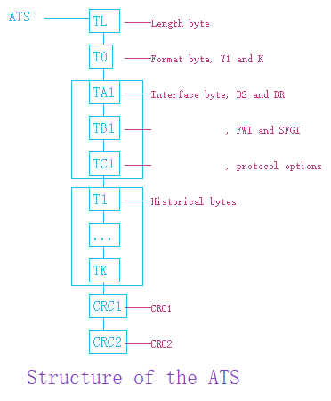
//-- - T0 ................... Format byte (Mandatory)
//-- - TA1, TB1, TC1, ....... Interface byte (Optional)
//-- - T1, T2, ... ,TK ...... Historical byte (Optional)
//-- - CRC1, CRC2 ........... Checksum (Mandatory)
//--------------------------------------------------------------------------------
//TL( Length byte ) = 14
//----This byte means ATS length(include CRC) = 22
//--------------------------------------------------------------------------------
//T0( The Format character ) = 75
//--![]()
//--Y1 : indicator for the presence of the interface characters
//-- TA1 is transmitted when b4=1
//-- TB1 is transmitted when b5=1
//-- TC1 is transmitted when b6=1
//-- b7 should be 0
//--FSCI : defines the maximum size of a frame accepted by the PICC(0-14, The default value of FSCI is 2)
//-- Informations provided by T0
//--T0 indicatd number of interface characters and FSCI
//----- The most significant half byte (b4, b5, b6) is named Y1 and indicates
//-------- with a logic level ONE the presence of subsequent characters TA1, TB1, TC1 respectively.
//----- The least significant half byte (b3 to b0) is named FSCI(0 to 14)
//--------The most significant half byte = 7( 0 1 1 1 ) means indicate has these interface bytes TA1 TB1 TC1
//----The least significant half byte = 5
//----![]()
//----means FSC = 64
//--------------------------------------------------------------------------------
//TA1 = A2
//----The most significant bit 7 codes the possibility to handle different
//------divisors for each direction. When this bit is
//------set to 1 the PICC is unable to handle different divisors for each direction.
//----The bits 6,5,4 code the bit rate capability of the PICC for the
//------direction from PICC to PCD, called DS. The default value shall be (000)b.
//------The bit 3 shall be set to (0)b and the other value is RFU
//----The bits 2,1,0 code the bit rate capability of the PICC for the direction
//------from PCD to PICC, called DR. The default value shall be (000)b.
//----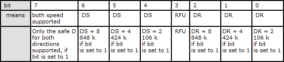
//----bit7 = 1, indicating that the both directions communication rate is 424K
//--------------------------------------------------------------------------------
//TB1 = A8
//----define the FWT(frame waiting time) and the SFGT(start-up frame guard time)
//----The most significant half-byte b7 to b4 is called FWI and codes FWT
//------The least significant half byte b3 to b0 is called SFGI and codes
//--------a multiplier value used to define the SFGT
//----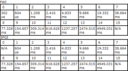
//----means FWT = 309.314 ms, SFGT = 77.328 ms
//--------------------------------------------------------------------------------
//TC1 = 03
//----The most significant bits b7 to b2 shall be (000000)
//------The bits b2 and b1 define which optional fields in the prologue field a PICC does support
//------The default value shall be (10)b indicating CID supported and NAD not supported
//----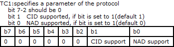
//----CID supported, NAD supported
//--------------------------------------------------------------------------------
//80 69 AF 02 04 01 36 00 02 0A 0E 83 3E 9F 00
//----is history bytes
//----Category indicator byte = 80
//------Compact TLV data object
//----------69 --- Tag: 6, Len: 9(pre-issuing data)
//------------Data: AF 02 04 01 36 00 02 0A 0E "꼀$è£6@$Å"
//----------83 --- Tag: 8, Len: 3(status indicator)
//------------LCS (life card cycle): 3E
//--------------Proprietary
//------------SW: 9F 00
//--------------9F 00 Is SW, means --- 成功,有超过0xff个字节的信息等待GET RESPONSE
//--------------------------------------------------------------------------------
//B0 BE
//--------------------CRC Correct