//ATR = 3B FD 11 18 00 B1 81 00 F1 20 4D 01 1F 01 88 99 99 99 99 99 99 99 99 99 99 99 99 CF
//Answer to reset data in units of characters (named 'character frame') for transmission
//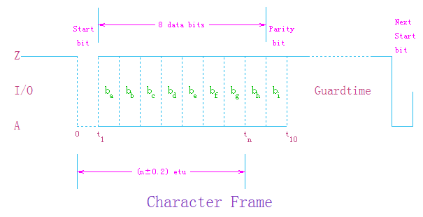
//----Prior to the transmission of a character, I/O shall be in state Z.
//----A character consists of ten consecutive bits:
//--------- a start bit in state A;
//--------- eight bits of information, designated ba to bh and conveying a data byte;
//--------- a tenth bit bi used for even parity checking.
//----During the answer to reset,The initial etu is 372/fi s where fi is in Hertz.
//----A data byte consists of 8 bits designated b1 to b8, from the least significant bit (lsb, b1) to the most significant bit (msb, b8).
//--------When searching for a start, the sampling time shall be less than 0.2 etu so that all the test zones are distinct from the transition zones.
//----The delay between two consecutives characters (between start leading edges) is at least 12 etu, including a character duration (10+/-0.2) etu plus a guardtime.
//----During the Answer to Reset, the delay between the start leading edges of two consecutives characters from the card shall not exeed 9600 etu.
//----------This maximum is named initial waiting time.
//----In the guardtime, the interface device and the card reamain both in reception, so that I/O is in state Z.
//----During the answer to reset,
//--------the following characters repetition procedure depends on the protocol type.
//--------This procedure is mandatory for cards using the protocol type T=0;
//--------it is optional for the interface device and for the other cards.
//--------The transmitter tests I/O (11+/-0.2) etu after the start leading edge:
//--------- If I/O is in state Z, the correct reception is assumed.
//--------- If I/O is in state A, the transmission is assumed to have been incorrect.
//--------The disputed character shall be repeated after a delay of at least 2 etu after detection of the error signal.
//------------------------------------------------------------
//----------<<<A reset operation results in the answer from the card consisting of the initial character TS
//--------------followed by at most 32 characters in the following order:>>>
//-- - T0 ................... Format character (Mandatory)
//-- - TAi, TBi, TCi, TDi ... Interface characters (Optional)
//-- - T1, T2, ... ,TK ...... Historical characters (Optional)
//-- - TCK .................. Check character (Conditional)
//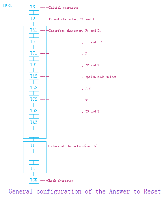
//-- TS : Initial character
//-- TO : Format character
//-- TAi : Interface character [ codes FI,DI ]
//-- TBi : Interface character [ codes II,PI1 ]
//-- TCi : Interface character [ codes N ]
//-- TDi : Interface character [ codes Yi+1, T ]
//-- T1, ... , TK : Historical characters (max,15)
//-- TCK : Check character
//--------------------------------------------------------------------------------
//TS( The Initial character ) = 3B
//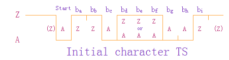
//--- Direct convention : (Z)ZZAZZZAAZ
//----where logic level ONE is Z, ba is b1 (lsb first),
//----equal to 3B when decoded by direct convention.
//--- Inverse convention : (Z)ZZAAAAAZ
//----where logic level ONE is A, ba is b8 (msb is first),
//----equal to 3F when decoded by inverse convention.
//----This character means Direct convention, high level is 1, low level is 0, LSB first.
//--------------------------------------------------------------------------------
//T0( The Format character ) = FD
//--![]()
//--Y1 : indicator for the presence of the interface characters
//-- TA1 is transmitted when b4=1
//-- TB1 is transmitted when b5=1
//-- TC1 is transmitted when b6=1
//-- TD1 is transmitted when b7=1
//--K : number of hitorical characters(0-15)
//-- Informations provided by T0
//--T0 indicatd number of interface characters and historical characters
//----- The most significant half byte (b4, b5, b6, b7) is named Y1 and indicates
//-------- with a logic level ONE the presence of subsequent characters TA1, TB1, TC1, TD1 respectively.
//----- The least significant half byte (b3 to b0) is named K and indicates the number (0 to 15) of historical characters.
//--------The most significant half byte = F( 1 1 1 1 ) means indicate has these interface bytes TA1 TB1 TC1 TD1
//--------------------( TA1, TB1, TC1, TA2, TB2 is global interface character,TC2 is Specific interface character )
//----The least significant half byte = D, indicates there are 13 historical bytes followed.
//--------------------------------------------------------------------------------
//TA1 = 11
//----Means has advanced baudrate, expression is "baudrate = f / ( F / D )"
//------f is frequency of the reader, in common use f = 3571200 (HZ)
//--------The F obtained by 'the most significant half byte of TA1 (FI)' look-up table
//--------The D obtained by 'the least significant half byte of TA1 (DI)' look-up table
//----FI = 01 , Check the following table, then F = 372
//------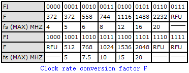
//----DI = 01 , Check the following table, then D = 1
//------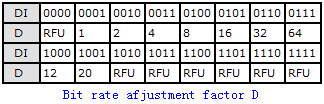
//----The recommended baudrate after reset is 9600
//--------------------------------------------------------------------------------
//TB1 = 18
//----TB1 is deprecated,bit 6-0 is used to represent card programming voltage and currentin early specifications
//------After the 2006 version, if TB1 appears, the value should be 0, indicating
//--------that the card does not use C6 to provide a programming voltage
//------The high bit of TB1 (8th bits) is reserved, shall be 0, and can be ignored by the reader
//----TB1 specify the Maximum programming current factor I(bit 6-5, base 0)
//--------and Maximum programming current voltage P(bit 4-0, base 0), defines the working state of VPP
//------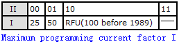
//--------bit 6, 5 = 0( 0 0 )
//--------bit 4-0 = 18( 1 1 0 0 0 )( 24 )
//----Programming voltage 0.0 V(TB2 present, indicate by TB2),current 25 MA
//--------------------------------------------------------------------------------
//TC1 = 00
//----Indicate extra gurard time integer(N)
//------The Guard Time is the minimum delay between the leading
//--------edge of the previous character, and the leading edge of the next character sent.
//--------T = 15 Present
//--------N = 0(0x00),extra guardtime EGT = 12 etu + N * etu indicated by TA1
//-------- = 12 etu + 0 * etu indicated by TA1
//--------------------------------------------------------------------------------
//TD1 = B1
//--TD1 : bit 7 - bit 4 indicator for the presence of the interface characters
//-- TA2 is transmitted when b4=1
//-- TB2 is transmitted when b5=1
//-- TC2 is transmitted when b6=1
//-- TD2 is transmitted when b7=1
//-- bit 3 - bit 0 : protocol
//-- Informations provided by TD1
//--------bit 7-4 = B( 1 0 1 1 ), means indicate has these interface bytes TA2 TB2 TD2
//--------bit 3-0 = 1, means transmit protocol T = 1
//--------------------------------------------------------------------------------
//TA2 = 81
//---------- bits 1 0 0 0 0 0 0 1
//--The presence of TA2 indicated card in special mode
//----TA2 bit 7( based 0 ) is 1, means unable to change the negotiable/specific mode
//----TA2 bit 4( based 0 ) is 0, means clock cycles as defined by TA1
//----The least significant half byte indicated the transmit protocol T = 1
//----special mode, card unable change the negotiable/specific mode, actual baudrate indicated by TA1, TA1 = 11 transmit protocol T = 01
//--------------------------------------------------------------------------------
//TB2 = 00
//----TB2 is global. The usage of TB2 is deprecated since the 2006 edition of the standard
//------which prescribes that cards should not include TB2 in the ATR
//------In the 1997 edition of the standard, TB2 (8th to 1st bit) encode PI2, which
//------when in range 50..250 (other values being RFU) encode VPP in increments of 0.1 V
//------and subsumes the coarser indication given by PI1 of TB1
//------Provision for TB2 did not exist in ISO/IEC 7816-3:1989
//----Programming voltage 0.0 V
//--------------------------------------------------------------------------------
//TD2 = F1
//--TD2 : bit 7 - bit 4 indicator for the presence of the interface characters
//-- TA3 is transmitted when b4=1
//-- TB3 is transmitted when b5=1
//-- TC3 is transmitted when b6=1
//-- TD3 is transmitted when b7=1
//-- bit 3 - bit 0 : protocol
//-- Informations provided by TD2
//--------bit 7-4 = F( 1 1 1 1 ), means indicate has these interface bytes TA3 TB3 TC3 TD3
//--------bit 3-0 = 1, means transmit protocol T = 1
//--------------------------------------------------------------------------------
//TA3 = 20
//----TA3 indicates the Information Field Size for the ICC( IFSC )
//------TA3 between 01 - FE is effective, 00 and FF to reserved
//--------
//----The maximum length of information field under T = 1 is 32
//--------------------------------------------------------------------------------
//TB3 = 4D
//----TB3 indicate BWI and CWI under T = 1
//------bit 7-4 is BWI and bit 3-0 is CWI
//--------BWI indicated BWT, BWT is the maximum delay between the
//--------leading edge of the last character of the block received
//--------by the card and the leading edge of the first character of the next block transmitted by the card
//--------the default BWI = 4(range 0-9)
//--------BWT = 11 etu + ( 2^BWI * 960 * Fd / f )
//------------current BWI = 4(0x04)
//--------------Fd = 1, means 372 clocks
//--------------1 etu = 372.0 clocks
//----Block waiting time BWT = 11 + ( 2^4 * 960 * 372 ) / 372.0 = 15371.0 etu
//--------CWI indicated CWT, CWT is the maximum delay
//--------between the leading edges of two consecutive characters in the block
//----------the default CWI = 13(range 0-15)
//----------CWT = (11 + 2^CWI) etu
//------------current CWI = 13(0x0D)
//----Character waiting time CWT = 11 + 2^13 = 8203 etu
//--------------------------------------------------------------------------------
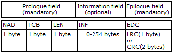
//TC3 = 01
//----T = 1 block transmit the error detection code
//------LRC longitudinal redundancy code
//--------xor from NAD to LRC inclusive shall give '00'
//------CRC cyclic redundancy code
//--------see ISO/IEC 13239
//----verify method is CRC cyclic redundancy code
//--------------------------------------------------------------------------------
//TD3 = 1F
//--TD3 : bit 7 - bit 4 indicator for the presence of the interface characters
//-- TA4 is transmitted when b4=1
//-- TB4 is transmitted when b5=1
//-- TC4 is transmitted when b6=1
//-- TD4 is transmitted when b7=1
//-- bit 3 - bit 0 : protocol
//-- Informations provided by TD3
//--------bit 7-4 = 1( 0 0 0 1 ), means indicate has these interface bytes TA4
//--------bit 3-0 = F, means transmit protocol T = 15, T = 15 not transmit protocol, Only the type of global interface bytes is specified
//--------------------------------------------------------------------------------
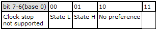
//TA4 = 01
//----TA4 indicate clock stop and classes after T = 15
//------
//------![]()
//----------bits = 0 0 0 0 0 0 0 1
//----bit 7,6 = 00, clock stop not support
//----bit 5-0 = 1, only A(5.0V)
//--------------------------------------------------------------------------------
//88 99 99 99 99 99 99 99 99 99 99 99 99
//----is history bytes
//--------------------------------------------------------------------------------
//TCK = CF
//--TCK correct